Connecting Arduino to Wifi using ESP8266
In this post I will try to show how to setup your ESP-01 WiFi module to connect your arduino to the Wifi.
ESP-1 WiFi module consists of ESP8266EX WiFi SoC (System on a Chip) which is developed by ESPRESSIF, a company based on China founded in 2008.
Espressif’s ESP8266EX can perform either as a standalone application or as the slave to a host MCU. When ESP8266 hosts the application, it boots up from it’s external flash memory. Alternatively, when ESP8266 is used as a slave, any microcontroller can use it through SPI/SDIO or UART interfaces as a WiFi adaptor.
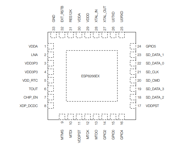
The figure shows the pin layout (top view) of the 32-pin QFN package of ESP8266EX which is the core of the ESP-01 WiFi module. The ESP8266EX WiFi SoC integrates a Tensilica L106. a extra-low power, max. 160 MHz 32-bit RISC processor. The ESP8266 WiFI SoC integrates a memory controller and memory units including SRAM and ROM. It should be noted that there is no programmable ROM in the SoC. Hence, user program must be stored in an external flash.
ESP8266EX implements TCP/IP and full 802.11 b/g/n WLAN MAC protocol. It supports Basic Service Set (BSS) STA and SoftAP operations under the Distributed Control Function (DCF).
ESP8266EX supports external flash theoretically upto 16 MB!! As is any other processor, the ESP8266EX has different peripheral interfaces, viz. SPI, I2C, I2S, UART, PWM, ADC and so on.
Okay, so much on ESP8266EX. Let’s come back to our ESP-01 module.
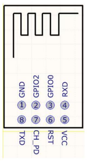
Before connecting the ESP-01 with Arduino, let’s first setup to see if our ESP-01 is working properly. This can be done by sending AT-commands to the ESP-01 using it’s RX-TX pins. To do this, we can use USB to TTL FTDI cable.
We can use ESP-01 in following two modes:
The first one is using ESP-01 as a slave of a microcontroller. The ESP-01 module is then controlled by the microcontroller by sending
The first way is using it as an independent SoC (System on a Chip) that doesn’t need another microcontroller to manipulate it as is usually done with an Arduino in case of other similar modules. The ESP-01 module when provided with appropriate voltage input (VCC 3.3V) and appropriate connection, is ready for serial communication, just like that! We can then send AT-commands to the ESP-01 and receive the result back using RX-TX pins of the ESP-01 module.
Last Updated: Saturday, 7 Mar, 2020 20:40:04 NPT
Author: Madhav Humagain (scimad)